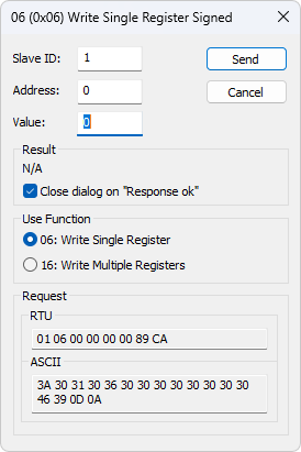

Standard Modbus function that writes 1 or more sequential registers from the specified starting address.Ĭommand īytes 0-1: 0-65535 (Transaction ID, echoed byīytes 4-5: 7 + 2*#Registers (Length, MSB-LSB)Ĩ-9: 0-65535 (Starting register address, MSB-LSB)īytes 10-11: 0-65535 (Number of registers to write, MSB-LSB)Ĭustom function that supports multiple frames, where each frame reads or writes 1 or more sequential registers. Response īytes 0-3: Echo of command bytes 0-3 (Transaction ID and Protocol ID)īytes 4-5: 3 + 2*#Registers (Length, MSB-LSB) Standard Modbus function that reads 1 or more sequential registers from the specified starting address.īytes 0-1: 0-65535 (Transaction ID, echoed by device)īytes 8-9: 0-65535 (Starting register address, MSB-LSB)īytes 10-11: 1-127 (Number of registers to read, MSB-LSB) Data: Data to write to registers are data read from registers.


Register: A 16-bit value pointed to by an address.Address: A 16-bit address that points to a 16-bit register.Function #: 3, 4, 6, or 16 are standard Modbus "holding" functions.Length: The number of bytes after the "Length" parameter, per the Modbus spec.Transaction ID: The device echos this value.Choose "Holding", which should tell the client to use function 3, 4, 6, or 16.įunctions 4 and 6 are seldom used, so we will focus our discussion on functions 3, 16, and MBFB: Some Modbus clients will ask you to specify "Coil", "Holding", "Discrete", or "Input". We also support a custom function called Modbus Feedback (MBFB) that can handle multiple reads & writes in a single packet. We support standard functions 3 (Read Multiple), 4 (Read One), 6 (Write One),Īnd 16 (Write Multiple). Modbus packets on the U3 and U6 are limited to 64 bytes, including the 2 zeros appended to the command. Packet size limits for the T4 are USB=64 and Ethernet=1040 bytes. Packet size limits for the T7 are USB=64, Ethernet=1040, and WiFi=500 bytes. With a read of a 32-bit (2 register) value, the value is returned MSW then LSW, where each word is returned MSB then LSB, so the 4 bytes come in order from most significant to least significant. With a read of a 16-bit (single register) value, the 1st byte returned is the MSB (most significant byte) and the 2nd byte returned is the LSB (least significant byte). Modbus is big-endian, which means the most significant value is at the lowest address. AIN0 is actually stored in 2 registers: the MSW (most significant word) is at address 0 and the LSW (least significant word) is at address 1. For example, AIN0 is defined as a 32-bit value that is read starting at address 0. In our Modbus Map we define some 32-bit values, and these are often referred to as a register, but when looking at the details of Modbus protocol, these are actually 2 Modbus registers. In the Modbus spec and in the function documentation below, a register is specifically a 16-bit value. Modbus Registers Are 16-bit LabJack Values Are One or More Modbus Registers The meaning of the registers are defined in the Modbus Map. Any function we support can be used to read or write values from any address. Each address points to a 16-bit value that might be readable, writable, or both. It consists of a register map with addresses from 0 to 65535. Our Modbus TCP interface is quite simple.

Sometimes a Server is called the Slave and a Client is called the Master. The U3 and U6 also have deprecated Modbus support.Ī Modbus TCP Client can send a command to the LabJack and get back a response. LabJack T-series devices (the T4 and T7) are Modbus TCP Servers. 28 Display formats such as float, double etc.Lengthy (and confusing) detail about Modbus TCP can be found at, but all the information actually needed is covered in the following.Test Center (Compose your own test strings).OLE Automation for easy interface to Excel using Macro language VBA.Multiple data formats such as float, double and long with word order swapping are available. Or you can change multiple registers/coils. If you want to change a single register, simply double click the value. You can read and write registers and coils from any window. For each window you simply specify the Modbus slave ID, function, address, size and poll rate. With the multiple document interface you can monitor several Modbus slaves and/or data areas at the same time.
Modbus poll 7.1 0 simulator#
Modbus Poll Crack is a Modbus master simulator designed primarily to help developers of Modbus slave devices or others that want to test and simulate the Modbus protocol.


 0 kommentar(er)
